DE Projects (Senior Year)
P2.1.5 AOI Circuit Design
Team Members: Michael B. Tuan L. and Arvin A.
Project Completed: December 1th, 2022
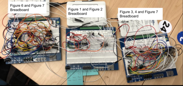
The entire goal of this project was to make a quiz grader that’s capable of checking four questions, a name, and a cheat condition. As such, we made a circuit that will model a four question quiz and that will check two other conditions of “cheater” and “name.” Since this quiz is out of four points, the outputs will be “full-credit” for getting all the four points, “half-credit” for getting exactly three or two points, or “no-credit” for getting exactly one or zero points. If the student answers a question correctly, add one point, up to four points but if the student is caught cheating, they will receive no credit and their points will be zero. Additionally, if the student does not put their name on the quiz, subtract one point from the total points otherwise, keep the score the way it is. My role in the project was to create the Full Credit system. The Full Credit output was only given if four questions were answered correctly, a name was given, and there wasn’t any cheating. Since there wasn’t much to work on with just the circuit, I did a majority of the documentation, such as the Design Brief, Design Specifications, and Final Design Description.
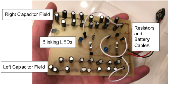
The final design has a total of six inputs and three outputs The inputs are the 4 questions, and name and cheating. Despite being in its simplest form, it has 56 logic gates. The components used in our circuits were mostly Logic Gates, specifically the AND, OR, and Inverter gates. Our team color coded our circuit to keep track of the gates and the various inputs. A problem we faced was the integration of the 3 circuits, as we had to use resistors to regulate the voltage flow between the different parts of the circuits. But since our boolean logic expressions are efficient and simplified, we don’t think that should be a problem in real life implementation.
P2.2.5 PCB Design
Created by Michael B.
Project Completed: February 30th, 2022
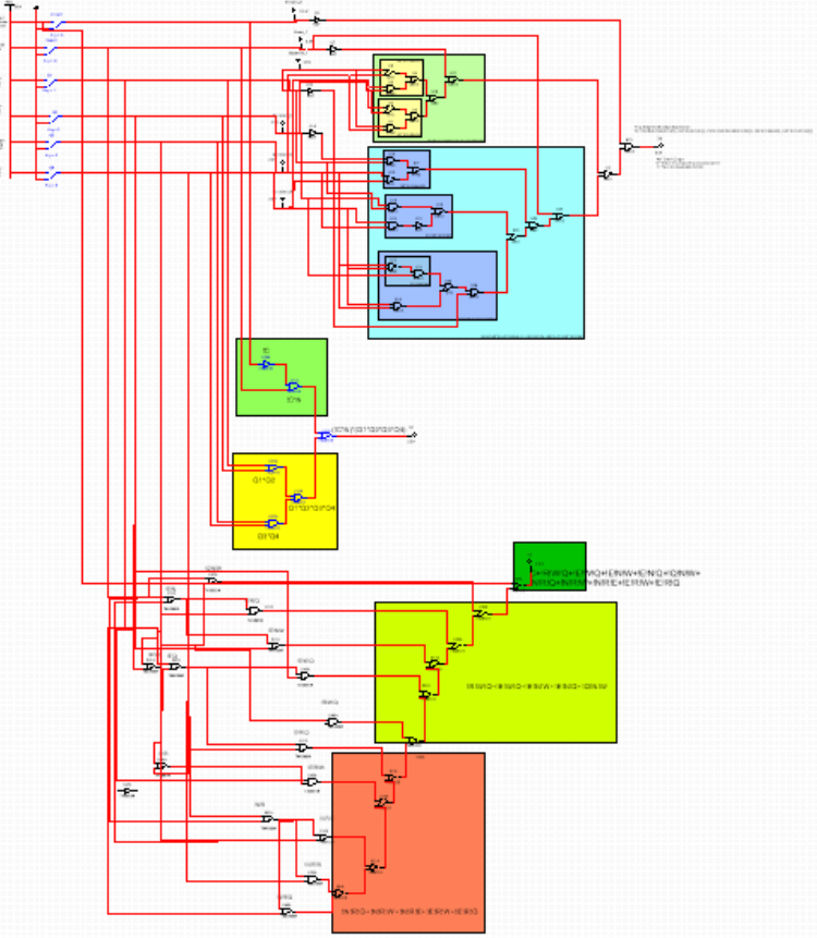
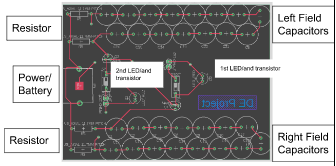
The fabrication process took a while. The beginning starting process, started with picking a circuit. When that was done, the next step was to build and assemble a schematic on Fusion 360. Afterwards, the task was to assemble it with a virtual circuit board. In succession, a mask must be created by heating glossy paper on a copper green board. However this can be spent with a sharpie. Next, the rest of the copper that doesn’t have ink or sharpie in them needs to be eaten away by ferric chloride. Following that, after some sandpapering to get rid of the ink and sharpie, some drilling of the holes of the components. Then, soldering the components through the holes to the board and the fabrication process is complete.
These pictures show the final circuit board, it contains all of the components in the original circuit but soldered together. Soldering now chemically binds them together. The circuit design is exactly the same as the virtual representation. The soldering job could have been better, yet it was able to function.
POE Projects (Sophomore Year)
POE Compound Machine Project
Team Members: Michael B. Nathan K. Noah H. and Anmol N.
Project Completed: December 8th, 2020
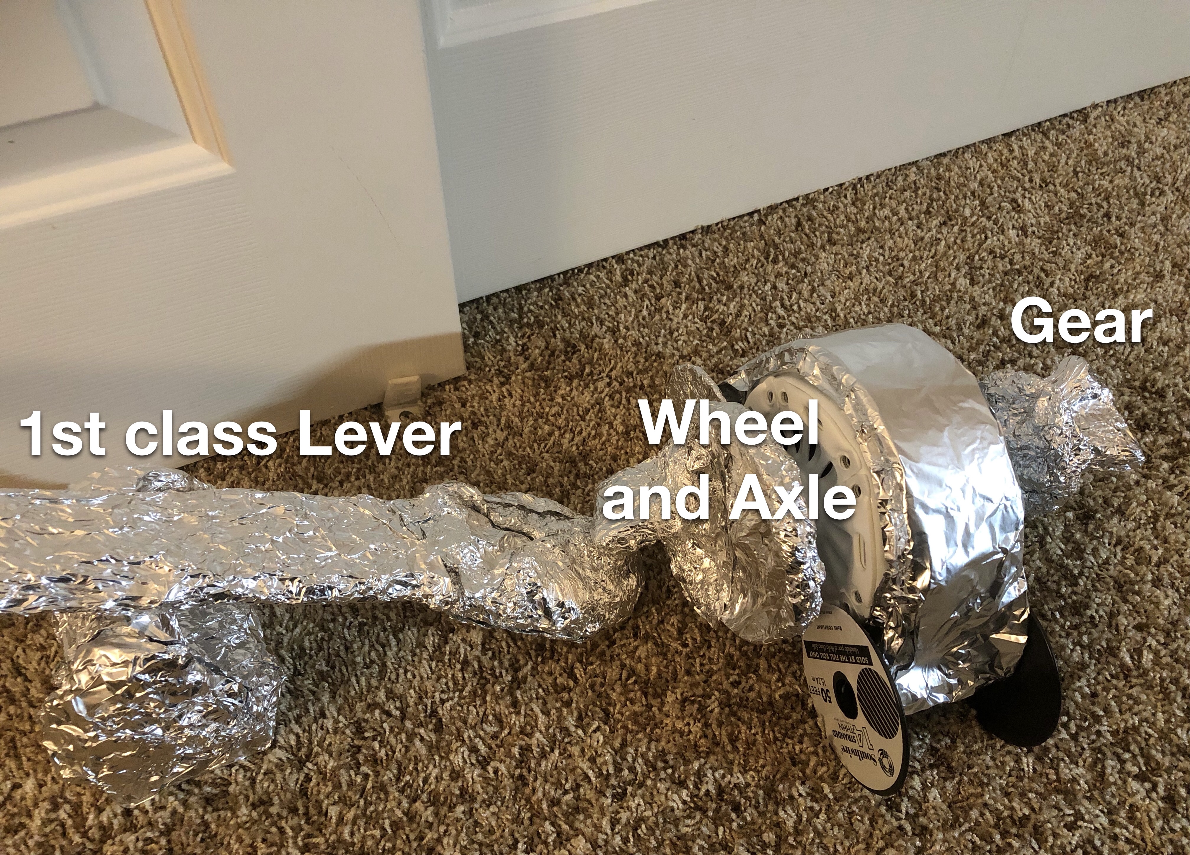
This is the final project for semester one. It took a period of a month. It was a combination of all we learned in the first few units. We separated the project into four sections and each section was three pieces. And each third of a section was a simple machine with an IMA. So a total of 12 simple machines made up this entire project. The types of simple machines were a wheel and axles, gear trains, levers, and pulleys. The total IMA for this project is 328.64.
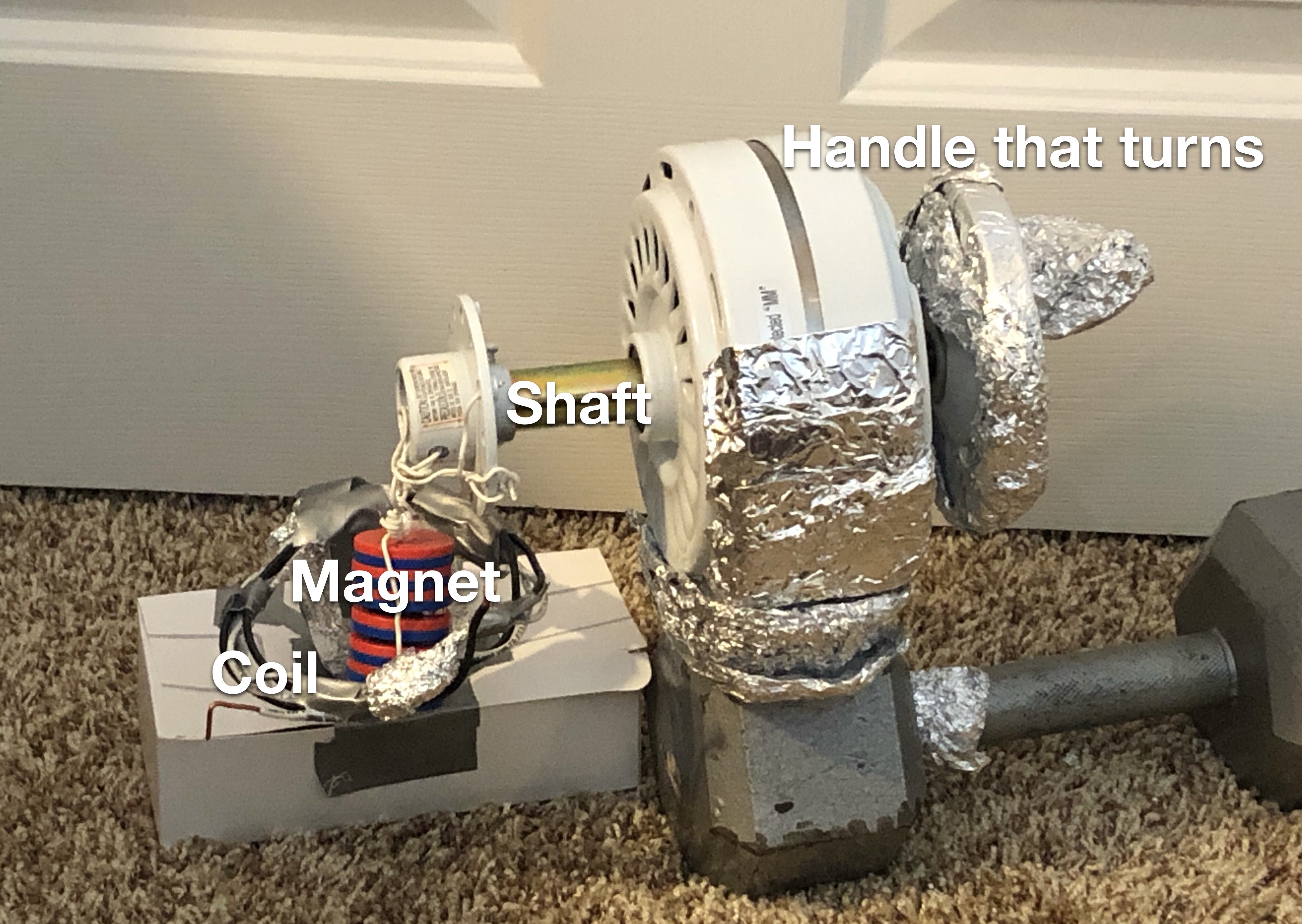
This compound machine is designed for the project's problem of capturing Santa by lifting his 250 pounds. This machine is triggered by Santa placing a 1 pound present on one side of a lever. The lever allows the wheel to move, and the wheel moves a gear. That gear moves a pulley that lowers a weight that activates a lever that knocks a ball off of it’s stand, and since the ball is attached to a pulley. That turns another pulley, that turns a wheel, and that turns a gear train. The output gear turns a pulley that lowers a weight that activates a lever that lifts Santa.
The prototype’s performance is supposed to increase over each section. The first section’s second mechanism has the least amount of friction, the axle can spin for a while after being spun. A potential inefficiency could be in the second section, where the ball can fall only a little bit off the pulley. In addition, the force is exerted during a short period of time. The performance of the machine might be affected by these things. Here is also a link for the Documentation.
POE Upcycling Project
Team Members: Michael B. Nathan K. and Ronith S.
Project Completed: March 8th, 2021
This was the first project of 2nd semester. I worked with Nathan and Ronith to create a line of products. The purpose was to make some useful products with recycled materials. The line of materials included, a small AC generator, a motor, and an electrical transformer. With these creations we conducted tests and realized they needed more work. Our intended consumers were going to be anyone in need of electrical equipment, from the big businesses to the everyday citizen.
The common theme among our products is electricity. Our first product is a small portable generator. Secondly, we have a small, easily assembled electric motor. Finally, we have an electric transformer. All of these products are mostly made with recycled materials.
We also tested our individual creations to see how good they were. The tests we did on our products were each sort of unique. With no clear instruction from the teacher concerning electrical performance, we set to thinking and formulated a plan. With the generator we had no physical multimeter to test the voltage or amps of the generator, so we decided to judge based on how the electricity jumps, and calculate a range of numbers from the distance the voltage jumps. With the electrical motor, we discussed and decided to see how many turns the motor turned based on the number of seconds that it was on. With the transformer, we would power one side of the transformer and judge the voltage with similar methods from the generator.When the results came in, we came up with improvements to our products. With the generator, the shaft was slow to turn due to a shaky base and foundation and the tests resulted in voltages in less than nine volts. For the electrical motor, the motor was unable to turn fully, as there were not enough coils, since too many would make it too heavy to spin, and the wire was too thick. Finally, concerning the transformer, the wires weren’t able to make a magnetic field at first, and using boxes and objects didn’t work. Once using two stainless steel water bottles, I was able to successfully make the transformer to work. I tested to see if the transformer worked by attaching a battery to the copper wire and tested for the voltage and got nine volts. for test one and eleven volts for test two. A link to our documentation is below.
CSP Projects (Freshmen Year)
CSP Programming Project
These are some of the programming projects I made in my high school Freshmen class, CSP Period 2. These projects are around what my programming skills are. I have experience with both the applications Scratch and App Inventor from this project. We worked on them in pairs to talk and build on each other's ideas to make and get a successful project. The process of coding these failed and failed again, but when they finally worked, we had a huge sense of accomplishment when we succeeded. These projects built up our stamina and our abilities in this field.
CSP Image Project
My idea was to create a geometric shape and then form a meme into that shape. This would create an image where parts of it are not visible. I decided to do this because it makes you guess what the meme was and, if you don’t know what meme it is, probably look it up. The images to the right satisfy the client’s request because it creates a mask of geometric shapes and applies it to an image. The client can also take part in the creative process of the creation of the image by changing the percentage of the side of the image. This parameter is optional so if it is not changed the code will still work. Since memes do not have a determined brand image or brand, the two images could be considered brand images or standard images. If I was given more time I would try to figure out more of the code to try to figure out why some of the images looked different then others when we put certain commands in the function. I also would have tried to figure out how to rotate certain parts of the mask to make better filters.